
Thermic-welded cover with flexible laminations


Thermic-welded cover with flexible laminations
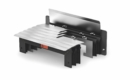
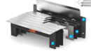
The P.E.I. thermic-welded standard covers are supplied also with flexible laminations, able to guarantee the same protection as the fixed ones, but they offer more flexibility in matching the supporting plan, thanks to their rotating capability.
PEI thermic-welded flat bellows are made up of:
- Steel laminations: they protect the shield from hot and incandescent chips.
- Bellows: (3) made with fabrics resistant to water, oil, coolants, dust and shavings.
- Supports in PVC: (4) they give rigidity to the entire bellows and are cut to size according to the profile of the customer’s rails.
- Connection flanges (1 and 2) for simple attachment to the machine.
Working position:
– Vertical
Data
Data
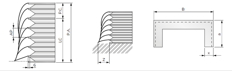
Definition of data for the calculation of the closed length of PEI thermic-welded flat bellows
P.A. = Open length
P.C. = Closed length
AP = Opening of 1 fold
LC (Stroke) = Open length – closed length
B = Bellows width
a = Bellows height
x = Fold height
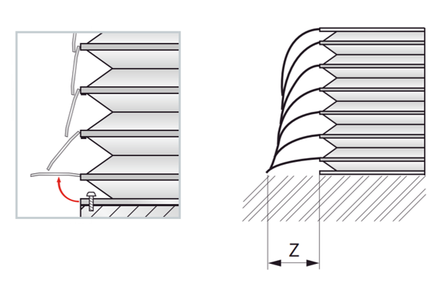
Overall dimensions of the flexible laminations as a function of the width of the bellow fold
| Bellows fold width = | x (mm) | 15 | 20 | 25 | 30 | 35 | 40 | 45 |
| Overall dimensions of the blade above the guide = | Z (mm) | 40 | 50 | 60 | 70 | 80 | 90 | 100 |
Formulae
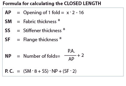
Indicative formula for the calculation of the closed length of thermic-welded flat bellows with flexible laminations
Contact our technical office
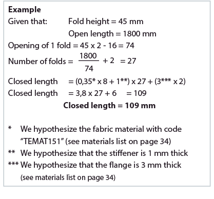
Example of calculation
* We hypothesize the material of the bellows with the code
“TEMAT151”
** We hypothesize that the thickness of the support is 1 mm
*** We hypothesize that the thickness of the flange is 3 mm
Standard materials
Standard materials
The fabrics selected by PEI have excellent mechanical resistance and resist bending and folding that occur during operation in the machine. They have excellent resistance to petroleum products, oils and strong abrasion, small welding splashes or incandescent material.
The fabric material list is currently being updated for the 2027 edition.
Contact info@pei.it to request the updated version.
Flanges
Fixing
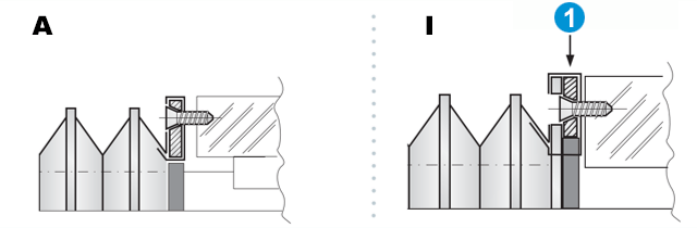
- = Flange
Attachment flange fixing systems
– Type A and Type I
- Solution with connection flange Type A: Flange covered by the fabric of the bellows (without last support)
- Solution with connection flange Type I: Painted flange fixed to the last support of the bellows
- Solution with sheet steel, aluminium or PVC flange
- Shape and drilling according to the customer’s design
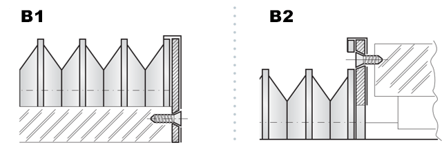
Attachment flange fixing systems
–Type B1 and Type B2
- Solution with connection flange Type B1: Flange that protrudes entirely from the shape of the bellows
- Solution with connection flange Type B2: Flange that protrudes externally with respect to the shape of the bellows
- Solution with sheet steel, aluminium or PVC flange
- Shape and drilling according to the customer’s design
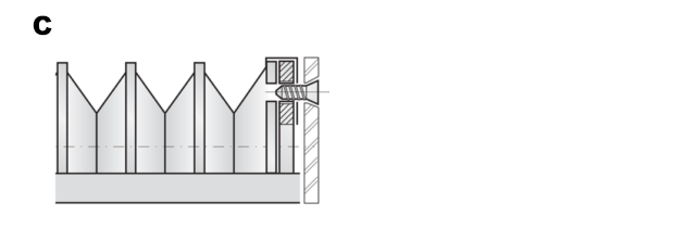
Attachment flange fixing systems
–Type C
- Solution with Type C attachment flange: Painted flange fixed to the last support of the bellows with threaded holes
- Solution with sheet steel flange
- Shape and drilling according to the customer’s design
- Threaded flange holes
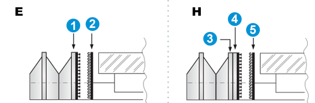
- = PVC cover stiffener
- = Strip of Velcro applied to the machine
- = PVC stiffener
- = Flange
- = Strip of Velcro applied to the machine
Attachment flange fixing systems
–Type E and H
Solution using VELCRO type quick fixing.
The task of the attachment flange is carried out by a PVC support to which VELCRO is applied. A Velcro strip is applied directly to the machine.
This solution offers the following advantages:
- Quick application and removal of the bellows
- Reduced cost
Recommended in dry work environments
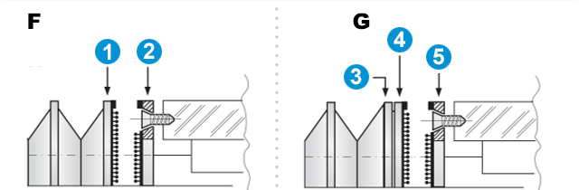
- = PVC stiffener
- = Flange
- = PVC stiffener
- = Flange
- = Counterflange
Attachment flange fixing systems
–Type F and G (Entire fold in PVC )
Solution through HIGH TENACITY quick fixing.
The attachment flange is made of sheet steel, aluminium or PVC, with shape and drilling according to the customer’s design.
This solution offers the following advantages:
- Quick application and removal of the bellows
- Perfect perimeter sealing by applying mousse.
Recommended in a humid working environment
Structures
Structures
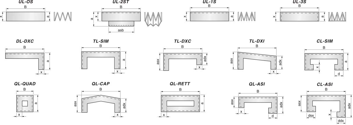
Standard structures for flat thermic-welded bellows
UL-OS = Folding fabric only
UL-2ST = Thermic-welded bellows with two weld seams and pull-out stop inside the bellows
UL-1S = One-sided bellow with PVC supports
UL-3S = One-sided thermic-welded bellows with three welded edges
DL-DXC = Thermic-welded bellows with two welded edges
TL-SIM = Thermic-welded bellows with three welded edges, symmetrical shape
TL-DXC = Thermic-welded bellows with three welded edges, asymmetrical shape
TL-DXI = Thermic-welded bellows with three welded edges, slanted shape
CL-SIM = Thermic-welded bellows with five welded edges, symmetrical shape
QL-QUAD = Thermic-welded bellow, square shape
QL-CAP = Thermic-welded bellow, roof shape
QL-RETT = Thermic-welded bellow, rectangular shape
QL-ASI = Thermic-welded bellows with four welded edge, asymmetrical shape
CL-ASI = Thermic-welded bellows with five welded edge, asymmetrical shape