Roll-up covers without canister
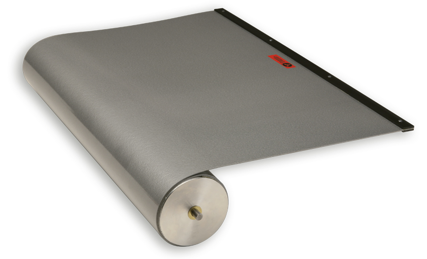
The PEI roll-up covers without canister are unique in their design and customisation for the user. The reliability of Roll-up Covers without canister guarantees up to 1,000,000 movements, thanks to the return motor equipped with multiple springs, which is reliable and operates with very high forward speed.
(Patented)
Data
Protection size
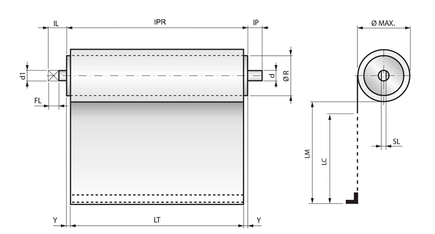
Data:
Ø Max = Maximum diameter all wrapped
SL = Tab thickness
LC = Course Length
LM = Max Length
LT = Floor width
Ø R = Winding roller diameter
IPR = Dimension protection
The IPR overall dimension of the roll-up cover depends on the Y dimension, which is calculated by our engineers. Contact our engineering department for any questions you may have.
Overall pin dimensions

Data:
d1 = Tab height
FL = Tab width
IL = Total tab dimension
IP = Pin dimension
d = Pin diameter
Ø R = Winding roller diameter
| Drive pin overall dimensions for STANDARD shutter roll-up protection | ||||||
| Ø R | d1 | IL | FL | SL | d | IP |
| 30 | 6 | 8 | 8 | 2,6 | 7 | 8 |
| 40-50-60-70-80-90-100-120 | 10 | 15 | 12 | 4 | 10 | 10 |
| Drive pin overall dimensions for SURE SPRING® roll-up guards | ||||||
| Ø ROLLERS | d1 | IL | FL | SL | d | IP |
| 39-52-71 | 10 | 15 | 12 | 4 | 10 | 10 |
PEI also manufactures drive pins according to the customer’s design
Support
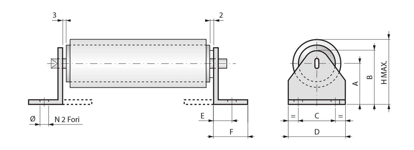
Standard dimensions of the supports for roll-up covers without canister.
| Overall dimensions of standard supports | |||||||||
| Code | A | B | C | D | E | F | Ø | Hmax | Materiale |
| 33 | 33 | 45 | 26 | 40 | 11 | 18 | 6,5 | 59 | galvanized Fe 15/10 |
| 50 | 50 | 62 | 26 | 40 | 11 | 18 | 6,5 | 93 | galvanized Fe 15/10 |
| 60 | 60 | 76 | 36 | 50 | 15 | 22 | 6,5 | 112 | galvanized Fe 20/10 |
| 80 | 80 | 96 | 42 | 60 | 17 | 26 | 6,5 | 151 | galvanized Fe 25/10 |
| 119 | 119 | 136 | 54 | 106 | 37 | 70 | 10 | 225 | galvanized Fe 40/10 |
Assembly
Position of vertical works
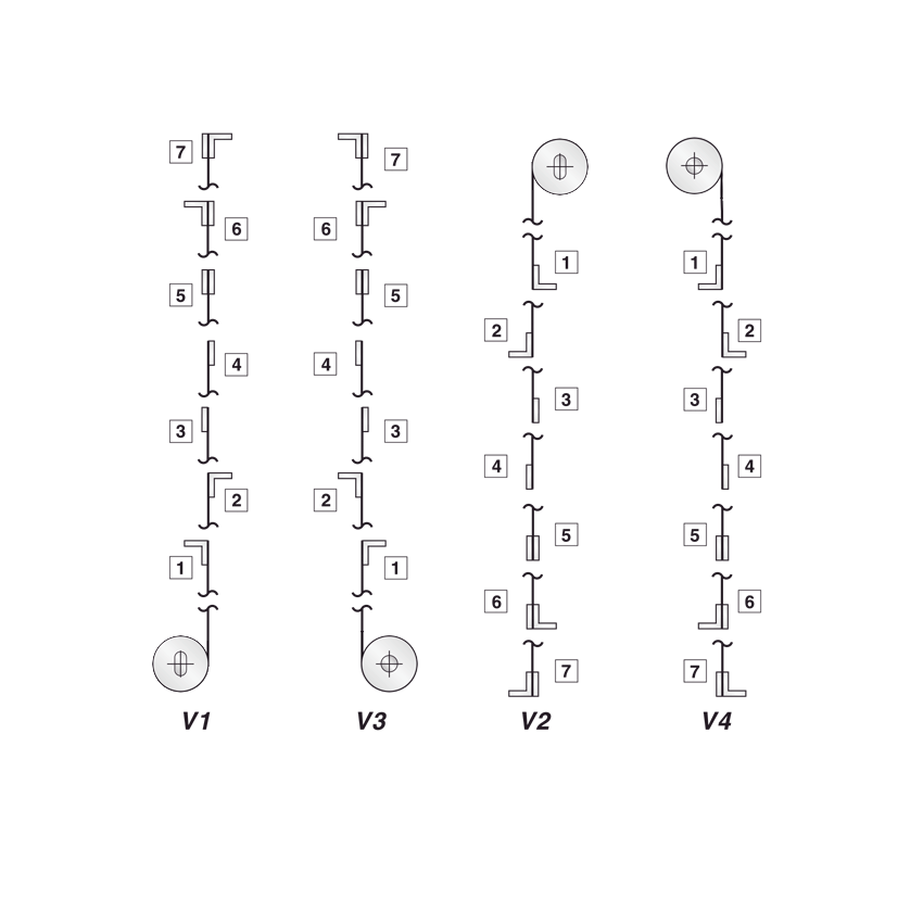
Assembly diagrams
This diagram is valid for all roll-up protections and represents:
- Terminal type
- Direction of exit of the floor
- Position of the terminal on the floor
- Pin / tab view
Horizontal working position
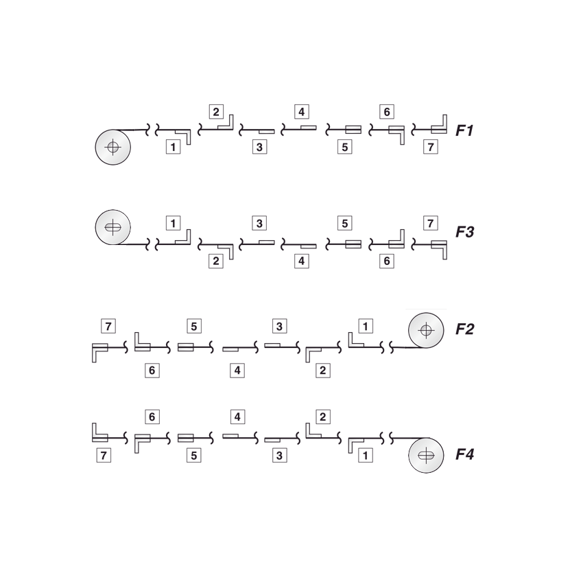
Assembly diagrams
This diagram is valid for all roll-up protections and represents:
- Terminal type
- Direction of exit of the floor
- Position of the terminal on the floor
- Pin / tab view
Fixing terminals
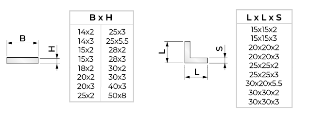
The belt fastening terminals on the machine are made of steel or aluminium strips and angles, drilled at the customer’s request
Position of works

O = Horizontal
F = Frontal
V = Vertical
Mechanism
SURE-SPRING®
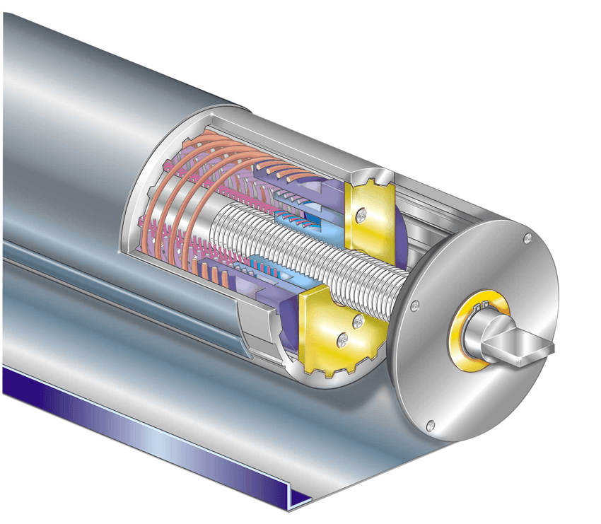
SURE-SPRING® mechanism
The P.E.I. patented design known as SURE-SPRING® represents the most advanced level of technical innovation in the field of roll-up covers.
- Suitable for high speed operation
- The multiple springs remain coaxial
- Reduced overall diameters
- Advancement speeds of up to 150 m/min
- Acceleration of up to 2 g
- 2,000,000 movement guaranteed
- Secure attachment of the band to the tube, because no adhesive products are used
- Quick and easy maintenance
- Also suitable for use in work environments where strongly aggressive chemicals are applied.
SURE-SPRING® HP VERSION
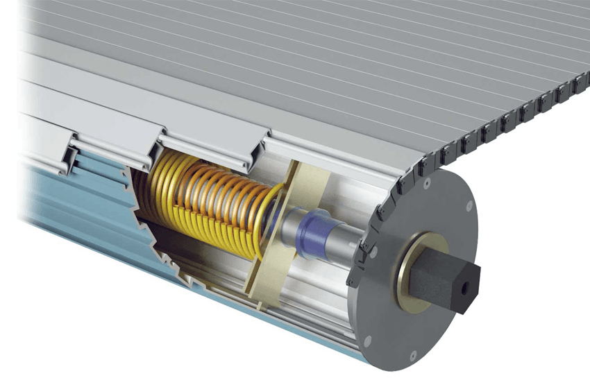
SURE-SPRING® Mechanism HP VERSION
The SURE-SPRING HP winding mechanism is the answer to the elevated power required to wind up large size protective covers.
An optimal dimensioning of the springs guarantees the tensile force required for moving“J” Series apron covers
Translation of motion
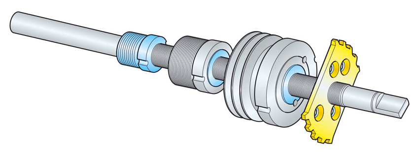
The rotary movement of the tube in relation to the fixed central shaft is transmitted by a sliding spline.
This system compensates for the elongation of the multiple springs by moving the spring mounting point axially along a threaded shaft.
Innovative characteristics
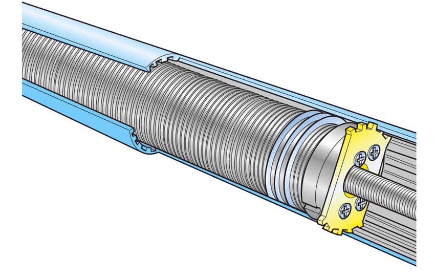
This new system allows the multiple springs to work according to an ideal geometry, keeping their coils properly spaced.
Fastening
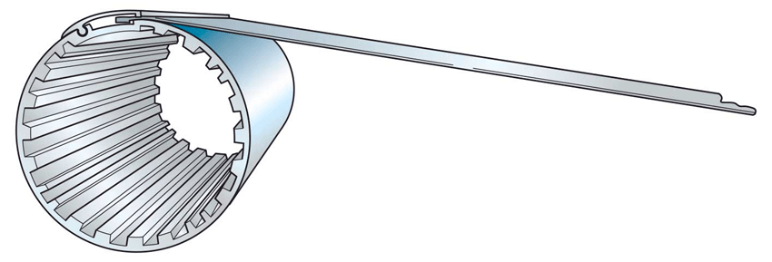
This is the most reliable system for insuring a secure mechanical fastening between the band to the tube.
Scheme
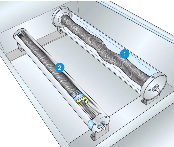
SURE-SPRING® operation diagram
- In Mechanism 1 (traditional system) the springs are rigidly attached to the fixed caps at the ends of the shaft. In this system the springs helically twist and snake while
winding or unwinding, causing obvious problems of friction and wear between the coils as well as between the coils and the central shaft. - In Mechanism 2 (SURE-SPRING® system) the springs are attached to a special moving cap, which slides lengthwise while winding and unwinding, keeping the spring coils packed and concentric at all times. This spring configuration avoids most of the wear mentioned above, allowing better performance and a much longer operating life-span for the spring mechanism.
CERAMIX Band
CERAMIX
CERAMIX Band
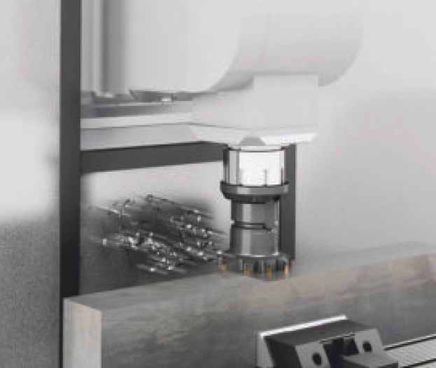
Aerospace technology in machine tools: a potent and cost-effective innovation
• Band material covered by a high ceramic polymer coating.
• Highly resistant against the impact of hot shavings during dry-working.
• It is an excellent abrasion resistance and shear strength and is recommended for the use of mineral oils.
• CERAMIX band material has a thickness of 1,8 mm and weighs 2 kg/sqm.
• It is antistatic.
This kind of band can be installed on any P.E.I. roll-up cover with mechanisms from 70 mm tube diameter
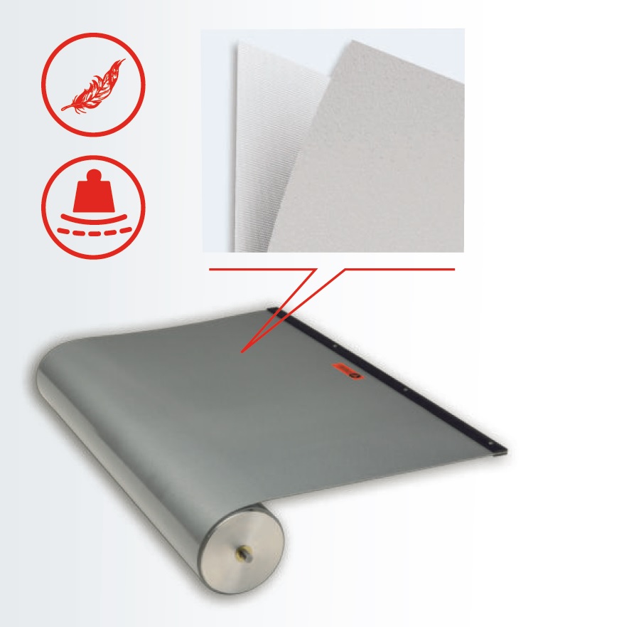
CERAMIX LIGHT
CERAMIX LIGHT Band
Identical resistance at half the weight
• CERAMIX LIGHT offers all the characteristics of CERAMIX but at a thickness of 0,9 mm and 1 kg weight per sqm.
• Antistatic.
• Suitable for roll-up covers with mechanisms from 20 mm tube diameter.
CERAMIX LIGHT

CERAMIX
- A glance through the microscope shows a mesh of ceramic particles which protect their own composite material against the strong impact of shavings.
Documentation
Fill out the questionnaire with the characteristics of your protection


